10+ fire pump installation diagram
57 GULSHAN AVENUE CWS-A19 DHAKA-1212BANGLADESH. March 7 2022 by Heather Septer.
Key Considerations In Fire Pump Design And Installation
Where the centerline plane is parallel to a horizontal split-case fire pump shaft the elbow or tee needs to be located a distance at least 10 pipe diameters from the suction flange.

. In a fire installation there can be one or more fire pumps put into operation as a duty assist 50 and standby pumps. 2 The pump casing shall be made of cast iron. Fire pumps are typically sized by pressure range.
The purpose for the 10x distance is to prevent turbulent flow from entering the fire pump and impeller which can cause wear and cavitation over time. Download Fire Pump Room AutoCAD Layouts. The casing shall be sound free of.
A circuit breaker designed for installation in a normal power supply circuit upstream of thecircuit breaker in a fire pump controller see diagram 2 should be selected with aninstantaneous trip. To meet the demand the fire pump s ize should be at least 400 gpm rated at 51 psi 100 psi 49 psi city pressure 51 psi. The fire pumps have been.
Suction Valve and Discharge Valves which are typically gate valves that can be totally open or totally. A jockey pump is a small pump connected to a fire sprinkler system to maintain pressure in the sprinkler pipes. Firetrol Fire Pump Controller Wiring Diagram.
On completing the adjustment of alignment dowel pins are inserted. Pump rooms containing fire pump equipment require special design as outlined in NFPA 20. This is to ensure that if a fire-sprinkler is activated there will be.
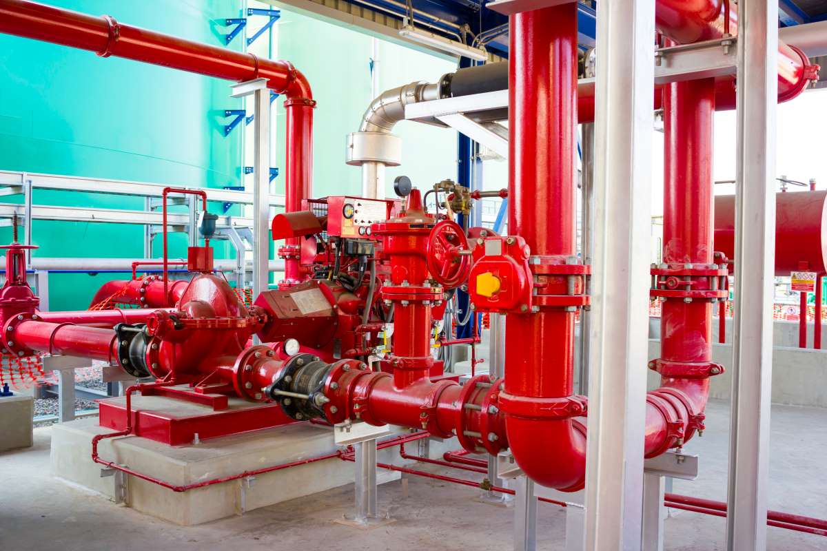
The pump room must be provided with a door and unobstructed passageway large enough to allow removal of the largest piece of equipment. For this blog we feature an installation in Phoenixville PA installed by H H Systems Inc. The fire pump delivers the water via the pipe system to the fire.
A wiring diagram is an easy visual representation with the physical connections and physical layout associated with an electrical system or circuit. F Page 5 Of 12 INSTRUCTION MANUAL 15-13A FOR Date. Protect conductors from overcurrent in accordance.
You shall install transformers installed to step up or step down the voltage serving a fire pump to comply with NEC Art. Fire pumps shall be located within. As we know many.
The component hardware in the Typical Pump Installation Set Up includes. 6 INSTALLATION OF FIRE PUMPS 61 The capacity of the fire pump should be carefully chosen to meet the maximum requirement for the risk 2. This Drawing Design and associated Technical.
It shows what sort of electrical. 1- Gate valve 2- check valve 3- Suction header 4- Discharge header 5- Diesel pump 6- Jockey pump 7- Electric pumps 8- Pressure relief valve 9- Alarm check valve 10- Water flow. We want good work recognized.
May 1 2000 FIRE PUMP 72 Case where alignment is checked by. The installation must follow the requirements of NEC 2306 which calls for you to either place the conductors below 2 inches of concrete encase conduit in 2 inches of concrete. The installation is of a Peerless horizontal.
Pump rooms may be implemented in. These supervisory conditions are verified by the fire protection and electrical experts during commissioning of a fire pump at the installation site. Product description full voltage starting electric fire pump controllers fta pdf free ft0f.
If your suction size is 12. Pumps shall be supplied by an equipment manufacturer that has listed pumps for fire water service.

Dcec Engine 6bta5 9 F For Cummins Fire Pump Driving China Pump Driving Engine And Fire Pump Engine

Electrical Design For Fire Fighting Pumps Electrical Knowhow
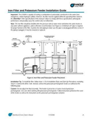
Hague Watermax

Peerless 4aef11 6 In Centrifugal Fire Pump Water Pump In Scappoose Oregon United States Ironplanet Item 6398270
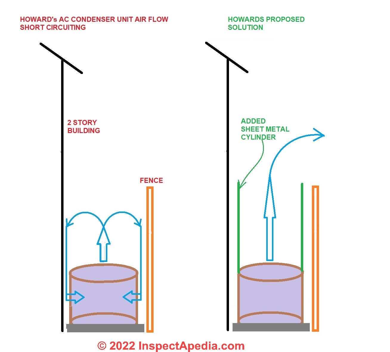
Hvac Clearance Distances Spacing Rules Between Air Conditioning Heating System Components And Other Building Features Or Mechanicals
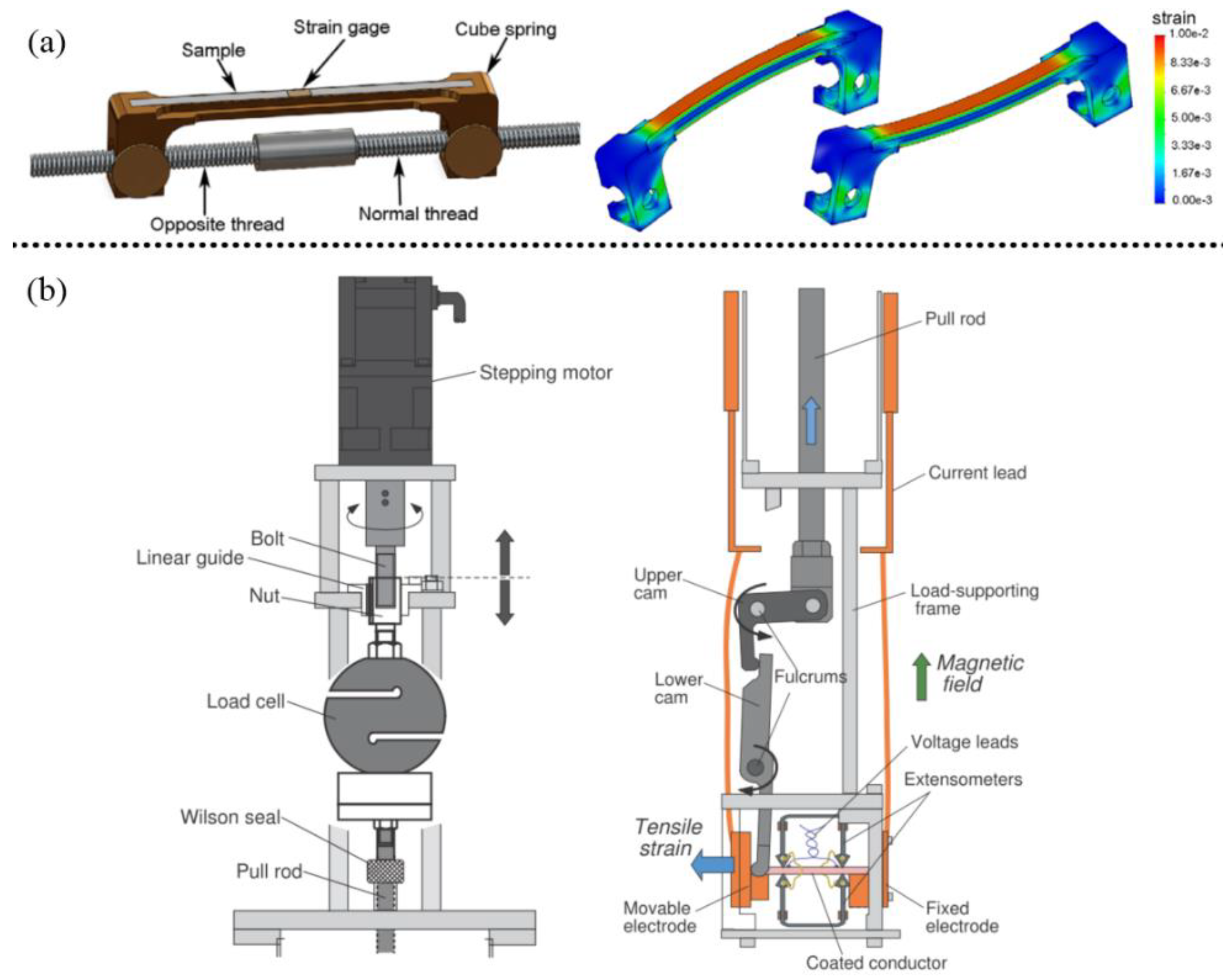
Nanomaterials Free Full Text A Review On Strain Study Of Cuprate Superconductors Html

Ecfr Appendix C To Subpart G Of Part 431 Title 10 Uniform Test Method For The Measurement Of Thermal Efficiency And Standby Loss Of Gas Fired And Oil Fired Instantaneous Water Heaters
Energies Free Full Text A Cost Effective Passive Active Hybrid Equalizer Circuit Design Html

Electrical Design For Fire Fighting Pumps Electrical Knowhow

Fire Sprinkler Designer Resume Samples Qwikresume

Electrical Design For Fire Fighting Pumps Electrical Knowhow

Grundfos Dosing Pumps Dde B Smart Digital S
Sniper Efi Installation Guide Holley Motor Life

Sprinkler Fitter Resume Samples Qwikresume

22 Idees De Anecl Electricite Auto Electricite Schema Schema Moteur

Electrical Design For Fire Fighting Pumps Electrical Knowhow

Peerless 4aef11 6 In Centrifugal Fire Pump Water Pump In Scappoose Oregon United States Ironplanet Item 6398270